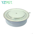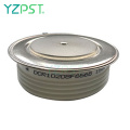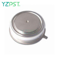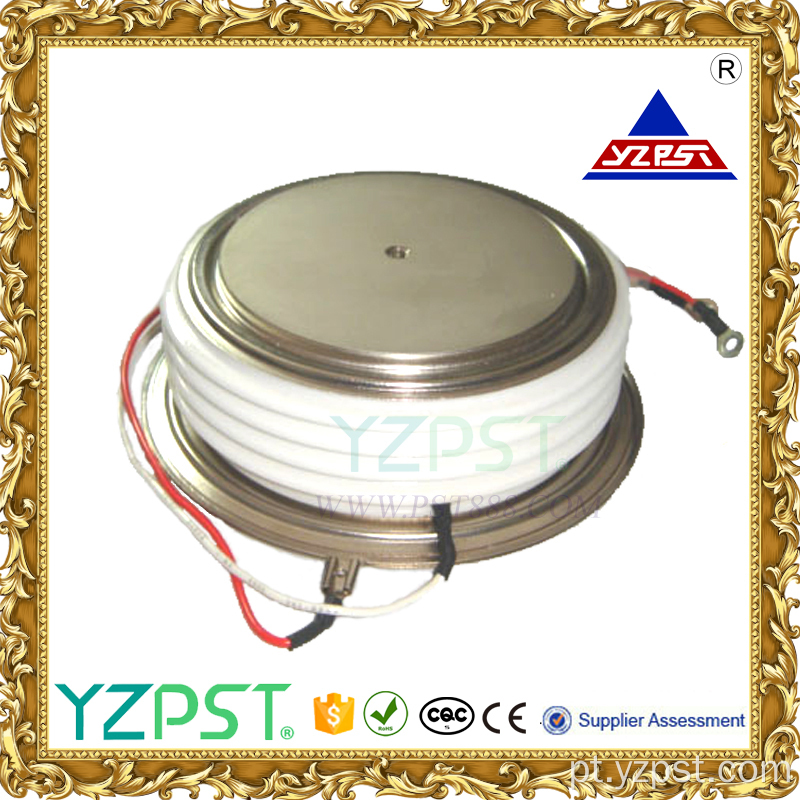
Controle de fase dos tiristores de 4000A 2500V KK4000
obtenha o ultimo preço| Tipo de pagamento: | L/C,T/T,Paypal |
| Incoterm: | FOB,CFR,CIF |
| transporte: | Ocean,Air |
| porta: | Shanghai |

| Tipo de pagamento: | L/C,T/T,Paypal |
| Incoterm: | FOB,CFR,CIF |
| transporte: | Ocean,Air |
| porta: | Shanghai |
Modelo: YZPST-KK4000A2500V
marca: YZPST
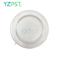
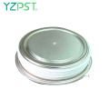
Controle de fase do tiristor de alta potência
YZPST-KK4000A2500V
Tiristor de controle de fase
Na temperatura ambiente especificada, uma certa tensão é adicionada entre o ânodo e o cátodo para permitir a corrente mínima de controle e a tensão necessária para que o tiristor alterne do estado desligado para o estado de condução.
|
Parameter |
Symbol |
Min. |
Max. |
Typ. |
Units |
Conditions |
|
Average value of on-state current |
IT(AV) |
|
4000 |
|
A |
Sinewave,180o conduction,Tc=70oC |
|
RMS value of on-state current |
ITRMS |
|
4900 |
|
A |
Nominal value |
|
Peak one cPSTCle surge (non repetitive) current |
ITSM |
|
55000
52000 |
|
A
A |
8.3 msec (60Hz), sinusoidal wave- shape, 180o conduction, Tj = 125 oC 10.0 msec (50Hz), sinusoidal wave- shape, 180o conduction, Tj = 125 oC |
|
I square t |
I2t |
|
5.5x10⁶ |
|
A2s |
8.3 msec |
|
Latching current |
IL |
|
1000 |
|
mA |
VD = 24 V; RL= 12 ohms |
|
Holding current |
IH |
|
500 |
|
mA |
VD = 24 V; I = 2.5 A |
|
Peak on-state voltage |
VTM |
|
2.30 |
|
V |
ITM = 3000 A; |
|
Critical rate of rise of on-state current (5, 6) |
di/dt |
|
800 |
|
A/ms |
Switching from VDRM£ 1000 V, non-repetitive |
|
Critical rate of rise of on-state current (6) |
di/dt |
|
300 |
|
A/ms |
Switching from VDRM£ 1000 V |

Gating
|
Parameter |
Symbol |
Min. |
Max. |
Typ. |
Units |
Conditions |
|
Peak gate power dissipation |
PGM |
|
200 |
|
W |
tp = 40 us |
|
Average gate power dissipation |
PG(AV) |
|
5 |
|
W |
|
|
Peak gate current |
IGM |
|
20 |
|
A |
|
|
Gate current required to trigger all units |
IGT |
|
300 200 125 |
|
mA mA mA |
VD = 6 V;RL = 3 ohms;Tj = -40 oC VD = 6 V;RL = 3 ohms;Tj = +25 oC VD = 6 V;RL = 3 ohms;Tj = +125oC |
|
Gate voltage required to trigger all units
|
VGT |
0.30 |
5 4
|
|
V V V |
VD = 6 V;RL = 3 ohms;Tj = -40 oC VD = 6 V;RL = 3 ohms;Tj = 0-125oC VD = Rated VDRM; RL = 1000 ohms; Tj = + 125 oC |
|
Peak negative voltage |
VGRM |
|
20 |
|
V |
|
Dinâmico
|
Parameter |
Symbol |
Min. |
Max. |
Typ. |
Units |
Conditions |
|
Delay time |
td |
|
2.0 |
|
ms |
ITM = 50 A; VD = 67% VDRM Gate pulse: VG = 30 V; RG = 10 ohms; tr = 0.1 ms; tp = 20 ms |
|
Turn-off time (with VR = -5 V) |
tq |
|
80 |
|
ms |
ITM > 2000 A; di/dt = 25 A/ms; VR³ -5 V; Re-applied dV/dt = 400 V/ms linear to 67% VDRM ; Tj = 125 oC; Duty cPSTCle ³ 0.01% |
|
Reverse recovery current |
Irr |
|
200 |
|
A |
ITM > 2000 A; di/dt = 25 A/ms; VR³ -50 V; Tj = 125 oC |
CARACTERÍSTICAS TÉRMICAS E MECÂNICAS E CLASSIFICAÇÕES
|
Parameter |
Symbol |
Min. |
Max. |
Typ. |
Units |
Conditions |
|
Operating temperature |
Tj |
-40 |
+125 |
|
oC |
|
|
Storage temperature |
Tstg |
-40 |
+150 |
|
oC |
|
|
Thermal resistance - junction to case |
RQ (j-c) |
|
0.012
|
|
oC/W |
Double sided cooled Single sided cooled |
|
Thermal resistamce - case to sink |
RQ (c-s) |
|
0.002
|
|
oC/W |
Double sided cooled * Single sided cooled * |
|
Mounting force |
P |
10000 |
12000
|
|
lb. kN |
|
|
Weight |
W |
|
|
3.5 1.60 |
Lb. Kg. |
|
Superfícies de montagem suaves, planas e lubrificadas
Nota: para contorno e dimensões do caso, consulte o desenho do contorno do caso na página 3 deste Dados técnicos

A: 100 mm
B: 150 mm
C: 127 mm
D: 35 mm


Número De Telefone: 86-514-87782298
Whatsapp: +8613805278321
Endereço: 3rd Floor, Weiheng Building No.20 B Area, Yangzhou, Jiangsu China
site: https://pt.yzpst.com


Privacy statement: Your privacy is very important to Us. Our company promises not to disclose your personal information to any external company with out your explicit permission.
Fill in more information so that we can get in touch with you faster
Privacy statement: Your privacy is very important to Us. Our company promises not to disclose your personal information to any external company with out your explicit permission.